Products
Low Temp. Absorption Chiller
The working principle of a low-temp. absorption chiller is illustrated in Fig. 3.2-1. The refrigerant vapor generated by the generator is cooled down in the condenser in the form of refrigerant water, which is then delivered via U-shape tube to the drip pan of the evaporator. It absorbs the heat of chilled water and lowers its temperature to the setting value, then refrigerant water evaporates to vapor and enters the absorber. After absorbing the vapor, the concentrated solution in the absorber becomes a diluted solution and releases absorption heat, which is taken away by cooling water to keep the absorption ability of the solution. Water chiller manufacturers focus on optimizing this process to ensure efficient cooling and minimize energy consumption.
The diluted solution generated in the absorber is delivered by a solution pump to a heat exchanger, where it is heated and then enters a generator. In the generator, the diluted solution is heated by hot water as a heat source (which flows inside the tube) to the boiling point and generates refrigerant vapor. Meanwhile, the diluted solution is concentrated into a concentrated solution, which comes to the absorber to repeat the continuously cycling process as above. Water chiller manufacturers ensure that the heat exchangers in these systems are designed for maximum efficiency, reducing energy loss during the heating process.
Cooling water is used to reduce the medium temperature in the absorber and condenser. After being heated, it is connected to the cooling tower system and returned to the unit for circulation after cooling. Water chiller manufacturers design the cooling system to ensure that the cooling water efficiently removes excess heat, enabling the chiller to maintain consistent performance.
The entire system relies on precise engineering to ensure that each component, from the heat exchanger to the cooling tower, works in harmony. Water chiller manufacturers continuously refine their designs to improve the durability and efficiency of these systems, making them suitable for long-term, high-performance operation.

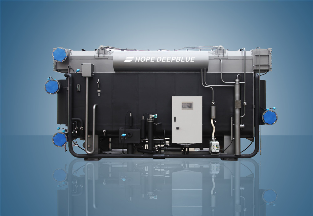
Low temp. absorption chiller is made up primarily of heat exchange devices (generator, condenser, evaporator, absorber, heat exchanger, and so on), automatic purge device, vacuum pump, solution pump, refrigerant pump, 3-way motor valve and electrical cabinet.


| No. | Name | Function |
| 1 | Generator | It concentrates the diluted solution from the heat exchanger into a concentrated solution using hot water or steam as a medium. Meanwhile, refrigerant vapor is generated and delivered to condenser, and concentrated solution flow to absorber.Design condition: Absolute pressure: ≈39.28mmHgSolution temp.: ≈80.27℃ |
| 2 | Condenser | It condensates refrigerant vapor supplied from the generator into refrigerant water. The heat produced during condensation is taken away by the cooling water.A rupture disk is installed at the refrigerant water outlet of condenser, it will work automatically when unit’s pressure is abnormally high, to protect unit from over-pressure.Design condition: Absolute pressure: ≈39.28mmHg |
| 3 | Evaporator | It cools down the chilled water for the cooling demand with the evaporated refrigerant water as a medium.Design condition: Absolute pressure: ≈4.34mmHg |
| 4 | Absorber | The concentrated solution in absorber absorbs refrigerant vapor supplied from the evaporator and the cooling water takes away the absorption heat. |
| 5 | Heat exchanger | It recycles the heat of the concentrated solution in the generator, therefore improving the system’s thermodynamic coefficient. |
| 6 | Auto-purge device | The two devices combine to make up an air purging system which pumps out the non-condensable air in the unit, ensures unit’s performance and maximizes service life. |
| 7 | Vacuum pump | |
| 8 | Refrigerant pump | It is used to deliver and spray refrigerant water evenly on the heat-conducting tube bundle of the evaporator. |
| 9 | Generator pump | Deliver solution to generator, realized the inner circulation in unit. |
| 10 | Absorber pump | Deliver solution to absorber, realized the inner circulation in unit. |
| 11 | Refrigerant bypass valve | Regulate the refrigerant water density in evaporator and drain out refrigerant water during unit shutdown. |
| 12 | Solution bypass valve | Regulate the refrigerant water density in evaporator |
| 13 | Density meter | Monitor refrigerant water density |
| 14 | 3-way motor valve | Regulate or cut off heat source water input |
| 15 | Control cabinet | For unit operation control |


