Products
Low Temp. Absorption Chiller
The working principle of a low temp. absorption chiller is illustrated in Fig. 3.2-1. The refrigerant vapor generated by the generator is cooled down in the condenser in the form of refrigerant water, which is then delivered via U-shape tube to the drip pan of the evaporator. It absorbs the heat of chilled water and lowers its temperature to the setting value, then refrigerant water evaporates to vapor and enters the absorber. After the absorber, the vapor, the concentrated solution in the absorber becomes diluted solution and releases absorption heat, which is taken away by cooling water to keep the absorption ability of the solution.
The diluted solution generated by the absorber is delivered by a solution pump to a heat exchanger, where it is heated and then enters a generator. In the generator, the diluted solution is heated by hot water as a heat source (which flows inside the tube) to the boiling point and generates refrigerant vapor. Meanwhile, the diluted solution is concentrated into a concentrated solution, which comes to the absorber to repeat the continuously cycling process as above. OEM chiller solutions are designed to optimize this process for greater efficiency and reliability. Cooling water is used to reduce the medium temperature in the absorber and condenser. After being heated, it is connected to the cooling tower system and returned to the unit for circulation after cooling.
The use of OEM chiller technology helps in improving the overall thermal management of the system. The system’s efficiency is boosted by the integration of precise heat transfer and cooling solutions. Furthermore, OEM chiller designs are customized to meet specific operational requirements, ensuring that all components work seamlessly together to deliver optimal performance. As a result, OEM chiller systems are ideal for reducing energy consumption while maintaining a stable and reliable cooling operation. After cooling, the refrigerant water returns to the unit for continued circulation, ensuring that the entire process is both efficient and cost-effective.

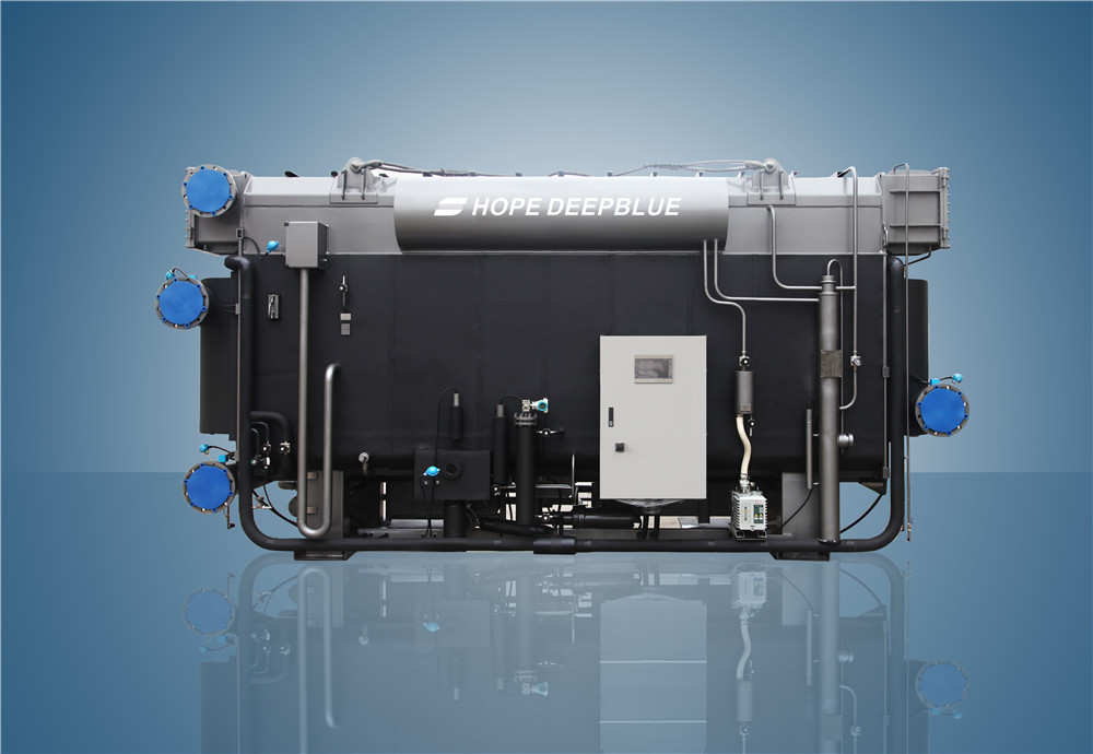
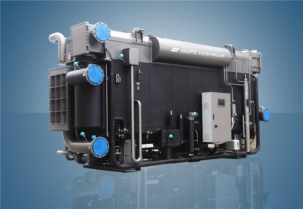
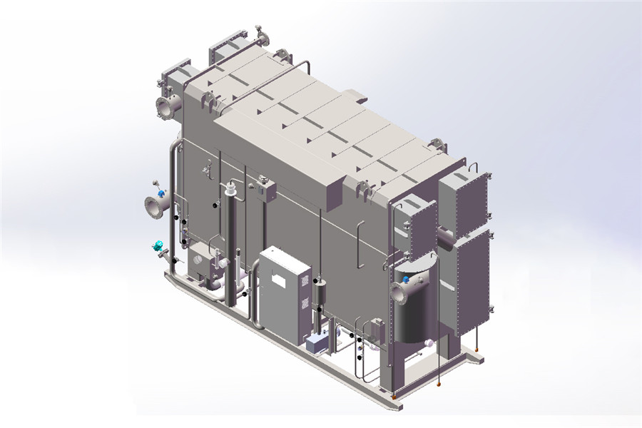
Low temp. absorption chiller is made up primarily of heat exchange devices (generator, condenser, evaporator, absorber, heat exchanger, and so on), automatic purge device, vacuum pump, solution pump, refrigerant pump, 3-way motor valve and electrical cabinet.
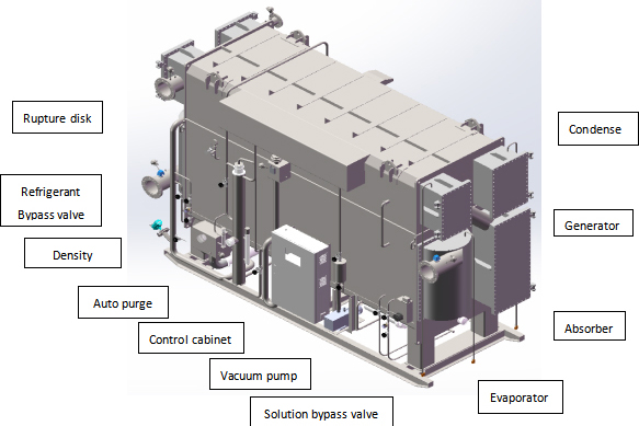
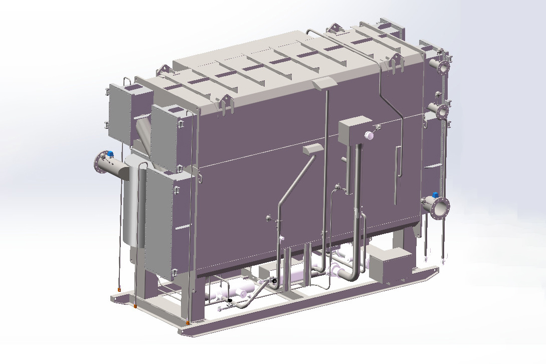
| No. | Name | Function |
| 1 | Generator | It concentrates the diluted solution from the heat exchanger into a concentrated solution using hot water or steam as a medium. Meanwhile, refrigerant vapor is generated and delivered to condenser, and concentrated solution flow to absorber.Design condition: Absolute pressure: ≈39.28mmHgSolution temp.: ≈80.27℃ |
| 2 | Condenser | It condensates refrigerant vapor supplied from the generator into refrigerant water. The heat produced during condensation is taken away by the cooling water.A rupture disk is installed at the refrigerant water outlet of condenser, it will work automatically when unit’s pressure is abnormally high, to protect unit from over-pressure.Design condition: Absolute pressure: ≈39.28mmHg |
| 3 | Evaporator | It cools down the chilled water for the cooling demand with the evaporated refrigerant water as a medium.Design condition: Absolute pressure: ≈4.34mmHg |
| 4 | Absorber | The concentrated solution in absorber absorbs refrigerant vapor supplied from the evaporator and the cooling water takes away the absorption heat. |
| 5 | Heat exchanger | It recycles the heat of the concentrated solution in the generator, therefore improving the system’s thermodynamic coefficient. |
| 6 | Auto-purge device | The two devices combine to make up an air purging system which pumps out the non-condensable air in the unit, ensures unit’s performance and maximizes service life. |
| 7 | Vacuum pump | |
| 8 | Refrigerant pump | It is used to deliver and spray refrigerant water evenly on the heat-conducting tube bundle of the evaporator. |
| 9 | Generator pump | Deliver solution to generator, realized the inner circulation in unit. |
| 10 | Absorber pump | Deliver solution to absorber, realized the inner circulation in unit. |
| 11 | Refrigerant bypass valve | Regulate the refrigerant water density in evaporator and drain out refrigerant water during unit shutdown. |
| 12 | Solution bypass valve | Regulate the refrigerant water density in evaporator |
| 13 | Density meter | Monitor refrigerant water density |
| 14 | 3-way motor valve | Regulate or cut off heat source water input |
| 15 | Control cabinet | For unit operation control |
